
CNC Tube Bending and Radius Rolling in Southern California
CAD-driven CNC tube bending and radius rolling in Fontana, California — tight-radius bends, sweeping rolls and clocked multi-plane geometries, repeatable across every reorder.
Tube bending design limits
| Machine | SOCO SB-63X4A-3S-V CNC tube bender |
| Materials | Steel, stainless and aluminum |
| Tube sizes tooled | 0.50, 1.00, 1.25, 1.50, 1.75 and 2.00 in OD; standard and non-standard CLR per the chart |
| Die match tolerance | Modeled CLR within ±0.05 in of a listed radius |
| Bend radius | Model to the published CLR chart |
| Between bends or rolls | Minimum 4 in |
| Straight before and after a bend | Minimum 3 in |
| Features near a bend | Keep at least 0.75 in clear |
| Distance from a coped end to a bend | Minimum 3 in |
| CAD formats accepted | SolidWorks (.sldprt), Parasolid (.x_t), STEP, IGES |
| Lead time | Quoted with every job |
CNC tube bending and radius rolling are driven directly from your CAD file, which keeps setup time down and makes results repeatable across reorders. Send a model in Parasolid, STEP or IGES and we generate the bend and roll instructions from it.
Tight-radius bends, large sweeping rolls and multi-plane clocked geometries all run on the same workflow. The one thing that decides whether a part can be built as drawn is the centerline radius — model to the CLR values we actually tool for, published in full on our chart, and the part comes off the machine matching the model.
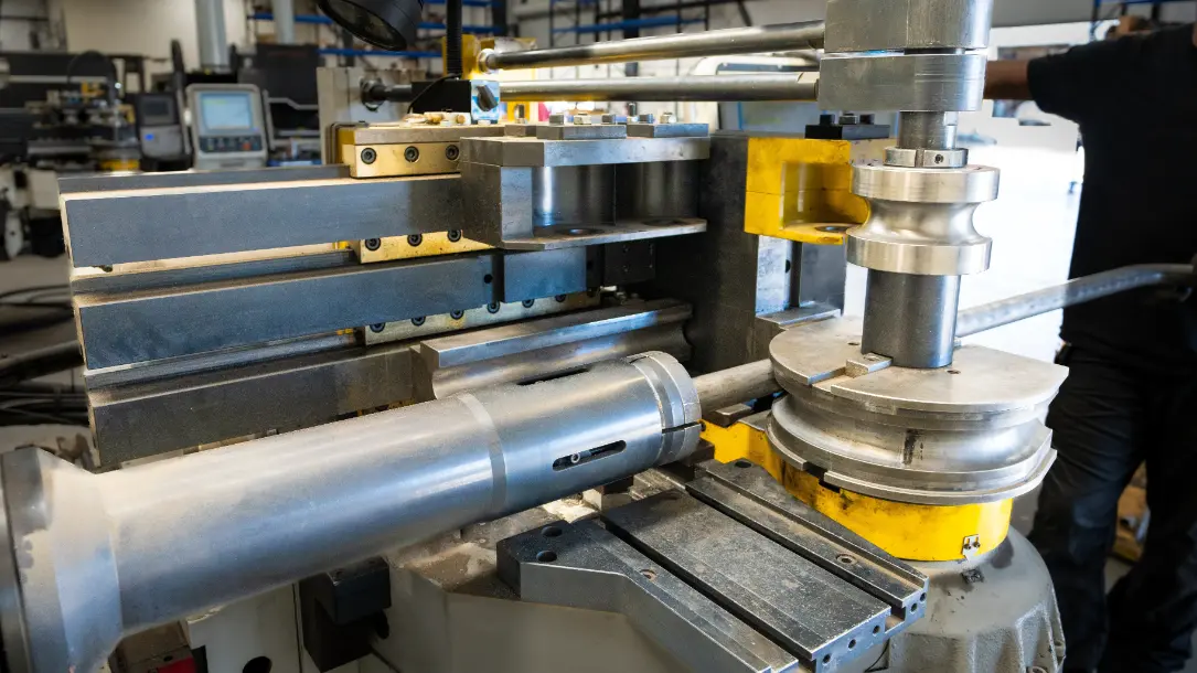
Bending runs on a SOCO SB-63X4A-3S-V CNC tube bender in steel, stainless and aluminum. We keep dies for 0.50, 1.00, 1.25, 1.50, 1.75 and 2.00 in outside diameter, each with a standard centerline radius and, on most sizes, a non-standard one. There is no extra charge for a non-standard die; the standard radius simply gives the most accurate and repeatable bend, so use it wherever the design allows. Your modeled CLR has to land within 0.05 in of a listed radius, and a diameter not on the chart has no in-house die, so ask before you design to it.
Tube is cut on our own tube lasers first, so bent parts arrive at the bender with copes, holes and part numbers already in them. Jobs are quoted by bends, bent tubes and setups plus material by the foot, from 20 ft sticks of stock; setups are charged once per unique part per run, so the per-piece price falls as quantity rises. Send every part of one material in a single multibody file so they share stock.
From Fontana we bend tube for fabricators and OEMs across San Bernardino and Riverside counties, Los Angeles and Orange County, and ship across Southern California. ITAR or export-controlled files should not go through the instant quote; email them to sales@calwestmfg.com.
Common questions
What bend radius should I design to?
Model to the exact centerline radius (CLR) we tool for. Our published CLR chart lists the standard and non-standard radii available for each tube size. Designing to a radius we do not have means the part cannot be bent as drawn.
How much straight tube do you need between bends?
Leave at least 4 inches between bends or rolls, and a minimum of 3 inches of straight tube before and after a bend. Closer spacing risks the clamp die marking the tube or disturbing the previous bend.
Can I put holes or features in a bend?
No. Holes, keys and markings inside a bend cause the tube to deform or crack. Keep features at least 0.75 inch away from the tangent point of the bend.
What tube sizes can you bend?
We keep dies for 0.50, 1.00, 1.25, 1.50, 1.75 and 2.00 inch outside diameter in steel, stainless and aluminum, each with a standard centerline radius and, on most sizes, a non-standard one. The full list is on our CLR chart. A diameter not on the chart has no in-house die, so ask before you design to it.
Is there a charge for a non-standard bend radius?
No. Standard and non-standard dies cost the same. The standard radius gives the most accurate and repeatable bend, so use it wherever the design allows and the non-standard one only when you genuinely need that radius.
Where is the tube bender and who do you serve?
Fontana, California, in the Inland Empire. We bend tube for customers across San Bernardino and Riverside counties, Los Angeles and Orange County, and ship across Southern California.
Before you send a file
- Official bend radius chart (CLR)
- Tube bending design rules
- Tube laser cutting
- Tubing in SolidWorks video course
Other services
- Tube Laser Cutting
- Plate Laser Cutting
- Press Brake Forming
- Welding
- CNC Machining
- Weldments
- Robotic Integration
- All services
Design guides and reference
- K-factor and bend radius chart
- Machine capacity and max sizes
- Plate stock sizes and steel grades
- How our instant quote prices a job
- Sheet metal in SolidWorks video course
- All design guides
- Quality and AS9100D certification
- Case studies
- Contact us
Get a quote on cnc tube bending
Check the CLR chart before you model, then send the file.
Request a quote →